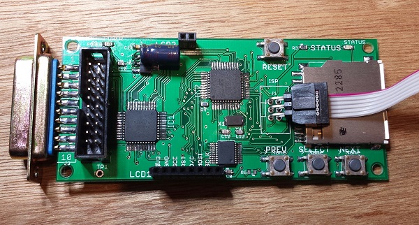
Here’s a handy trick I developed while searching for ways to reduce the cost and assembly time of Floppy Emu boards. The board has space for a 3 x 2 shrouded IDC header, where the AVR ISP cable should connect. But that connection is only needed once, the first time the AVR is programmed – all future software updates are loaded from the SD card using the bootloader. So why waste 75 cents and 30 seconds of soldering on a part that’s only ever going to be used once? It’s a small saving, I admit, but those savings add up.
OK, the programmer cable has a 3 x 2 female connector, and the board has an unpopulated footprint of 3 x 2 holes. Now what? My first attempt at a “no connector” solution was a straight 3 x 2 male header plugged into the cable connector, with the other end placed loosely inside the board footprint’s holes without soldering. By itself the fit was too loose, and the pins didn’t make reliable contact with the insides of the holes. If I pushed and twisted the connector with my finger, though, I could usually get all six pins to make contact long enough to successfully program the AVR. But as this only gave me one free hand, and didn’t work 100% reliably anyway, I gave up on that technique.
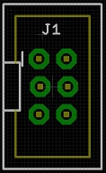
With board revision 1.1 I tried something new. Using Eagle, I created a staggered 3 x 2 header footprint, offsetting every other pin 5 thousandths of an inch from the centerline. I hoped this would help lock the pins tightly in place, keeping them pressed against the insides of the holes without solder and without my hand to brace it. But when the new boards came in, I was disappointed to find that while the staggered footprint was somewhat better than the original, it still didn’t work reliably. Sigh.
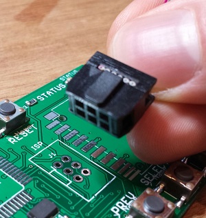
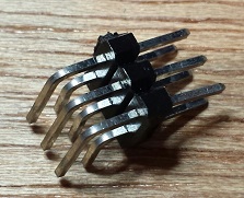
But every failure is just another step on the road to success! After more experiments, I finally hit upon a winning solution using a 3 x 2 right-angle header, with a small piece of scrap wedged under it for leverage. And I later found that the SD card holder is exactly the right size and in the right location to provide the necessary leverage, making for a quick and easy connection that’s 100% reliable with no soldering. I just plug one end of the 3 x 2 right-angle header into the programmer cable, and the other end into the holes in the board, with the connector and cable pressed against the top of the SD card holder. Once AVR programming is complete, I pull everything out and can re-use the parts for the next board. Hooray!