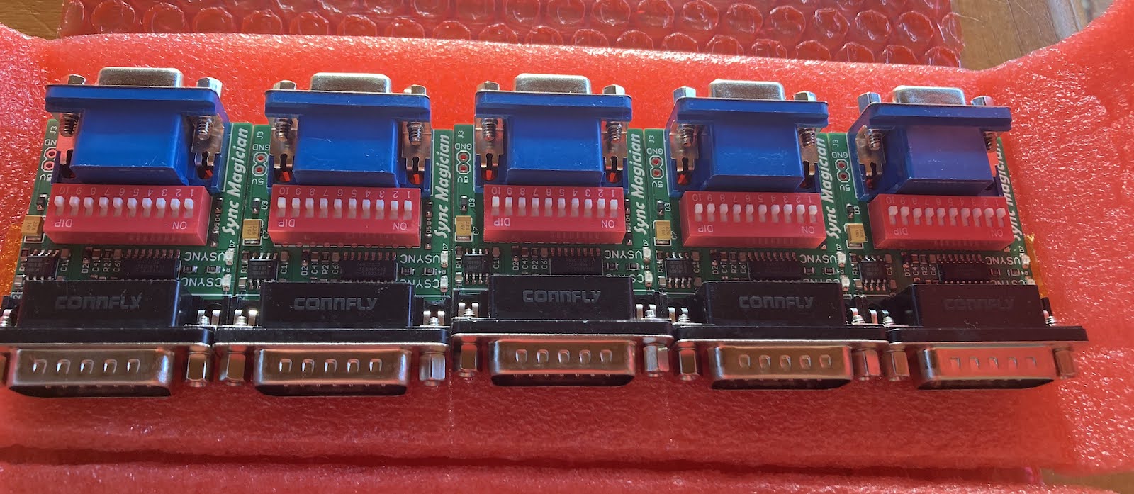
Elapsed time: 122 hours from design concept to finished product in my hands. Hey, it works!

Last week I wrote about my attempts to design a Macintosh-to-VGA video adapter with an integrated sync splitter, separating composite sync into the separate hsync and vsync signals expected by most VGA monitors. I bodged together a proof-of-concept circuit using an LM1881 chip, which sort-of worked on some of the monitors I tested. After that, my goals for this prototype PCB were:
sync detection LEDs: Two LEDs to visually indicate whether the Mac is putting out composite sync, separate sync, both, or neither.
self-powering: The chips in the adapter should be powered by rectifying the sync signals themselves, instead of requiring a separate 5V supply.
usable VSYNC: The extracted vsync signal from the LM1881, when combined with the original csync, should enable at least some monitors to work with my Mac that didn’t work before.
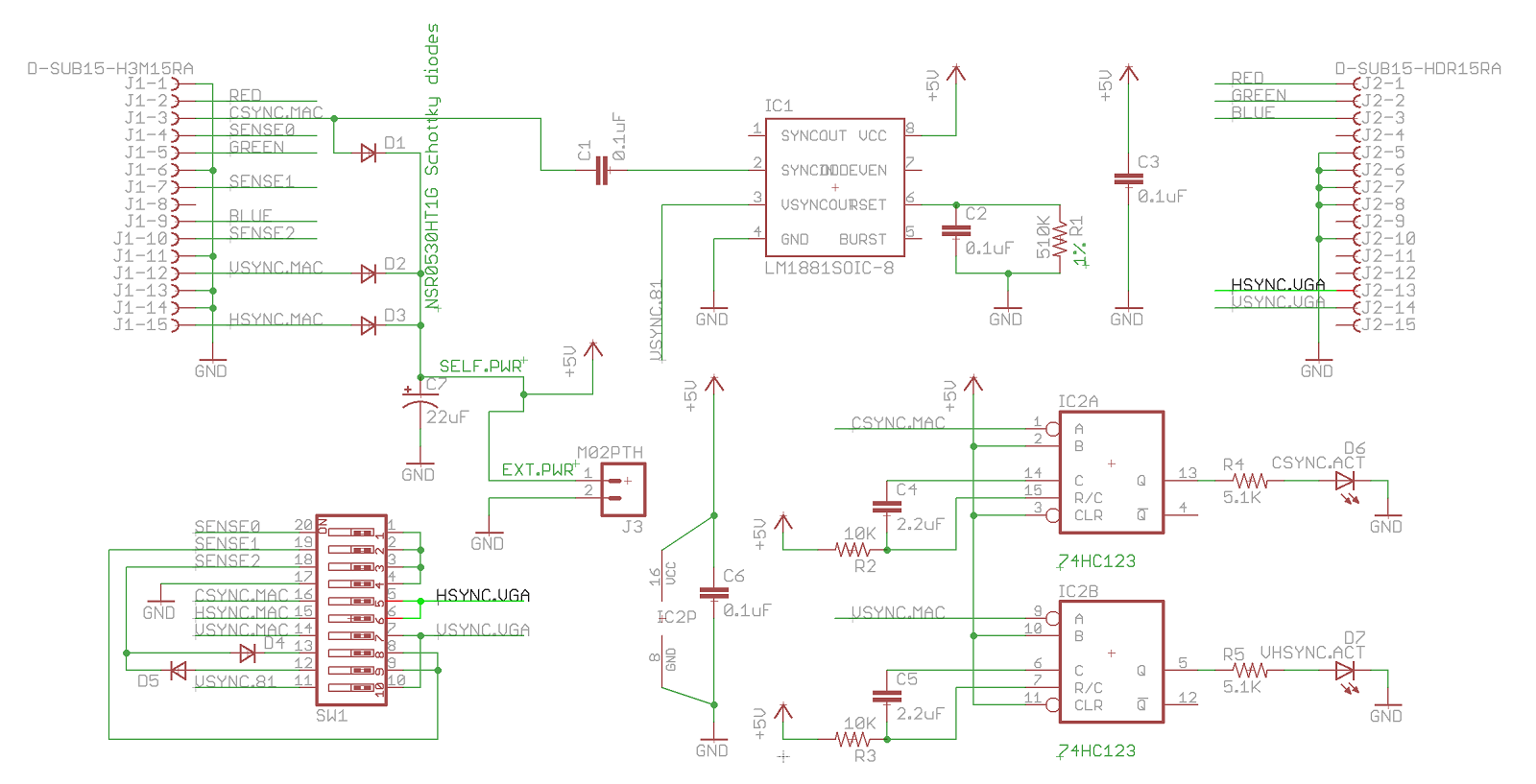
Here’s the PCB schematic:

There are two specific elements worth mentioning here. One is the LM1881 RSET resistor, which is 680K ohm in the LM1881 reference design, but I lowered it to 510K ohm here in a belief that this value would be more appropriate for Mac video resolutions.
The second element is the way the Mac’s csync signal is applied directly to the LM1881 video input at pin 2 (or “directly” through a blocking capacitor), instead of first passing through a resistor voltage divider to reduce csync to the approximate voltage level of a composite video signal. I experimented with both approaches, and an earlier schematic used the divider. But I think the combination of the resistor divider and the blocking capacitor formed an unwanted RC filter, resulting in oscillation and strange behavior. I could have taken further steps to address this, but since many other people have used 5V sync inputs with the LM1881, and it appeared to detect the sync just fine, I used the simpler approach without the divider.
Shiny New Prototype
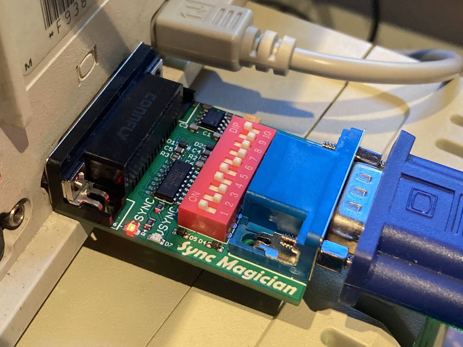
My first prototype was an ugly mess of wires and breakout modules, and it didn’t even try to implement sync detection LEDs or self-powering, so I was excited to try this new prototype PCB. I’m happy to report that sync detection works, for both csync and h+vsync. In an effort to reduce the adapter’s current consumption, the LEDs are powered with less than 1 mA of current, but are still easily visible. This is exciting and this feature alone is a great diagnostic tool. At this weekend’s Mactoberfest Meetup, you can bet I’ll be running around plugging one of these adapters into every Mac and Nubus video card that I can find, and making a list of which ones output csync, separate H+V sync, or both.

The self-powering also works. The self-powered supply voltage (diode rectified from the sync signals) results in a VCC about 4.09V. That seems to be high enough for the chips to work, but we’re in uncharted territory for the LM1881 and it may not work completely correctly at this voltage. The Schottky diodes used for rectifying should drop about 0.3V from 5V, so why isn’t VCC 4.7V? Well, there’s also a 180 ohm series resistor on each of the Mac’s sync outputs that will cause additional voltage drop, and the sync output drivers also have some internal resistance. Based on these numbers, I estimate the adapter is drawing about 3.3 mA (0.6V drop divided by 180 ohms) from each of the three sync signal outputs, or about 10 mA total.
It’s great that self-powering works, but the resulting VCC is lower than I would have hoped, and the dependency on that 180 ohm series resistor is troubling. If other Macintosh models and video cards have a larger series resistor or a higher internal resistance on their sync output, then self-powering might not work.
The vsync signal that’s output from the LM1881 has a voltage during its high parts of only about 2.65V. I think 2.65V is still high enough to be a valid logical high voltage when seen at the monitor, but it’s cutting it close. I might add a buffer or transistor here to bring the vsync signal all the way up to VCC, if it doesn’t increase the adapter’s current needs much.
There’s a second oddity about the LM1881’s vsync output with this prototype, aside from the voltage: the vsync pulse width is significantly longer than with the first protoype (about 16 lines versus 10), and it’s also variable (from about 15-17 lines on any given frame). The falling edge of the vsync pulse always comes at exactly the same spot relative to csync, but the time until the rising edge is variable. With my change of RSET from 680K ohm to 510K, the vsync pulse width in this new prototype should have been shorter than before, not longer. I’m not sure if this odd behavior is because of the lower VCC, or because one of my other component values is wrong, or what.
I can try all this again using a 5V external supply, instead of self-powering, and see how things change.
Field Testing
So does it actually work for separating hsync and vsync? The answer is yes, sort of. On my Dell 2001FP monitor it works, but the picture jumps up and down vertically by a couple of lines, probably due to the problems with VSYNC. I wouldn’t have guessed that the timing of vsync’s rising edge mattered much, so this is a little surprising.
I just received a Dell EL151FP monitor, which doesn’t work with the IIci normally, but does work via this adapter. Awesome! However once again there’s some vertical jitter.
My Viewsonic VG900b doesn’t work. This is the pickiest monitor in my stable, and it didn’t work with my first prototype either.
The Viewsonic 6 CRT works. This monitor doesn’t work with the Mac IIci normally, so this proves the adapter is doing something useful.
Goodbye LM1881, Hello MCU
As promising as this second prototype is, I’m not going to pursue this LM1881 design further. I’m not going to switch to a different sync-splitting chip either. It finally dawned on me that all the sync splitting chips are designed to do something much more complicated than I need: they’re meant to extract sync signals from a composite video signal that contains actual video data, chroma bursts, and negative-going sync, all at low voltage levels around 0.7V. But I don’t need any of that – I already have a 5V composite sync signal and I merely need to extract HSYNC and VSYNC from it.
After giving it some thought, I decided that the best path forward is to use a microcontroller to process the input sync signals, extract HSYNC and VSYNC, turn on the activity LEDs, and do anything else that’s needed. This will create some new challenges like clock-based jitter and VCC-imposed limits on clock speed, but it will turn this into more of a firmware plus circuit design problem, instead of a “read the datasheet” problem involving some complicated sync chip designed for a different purpose than mine.
I’ve already had some success with testing this approach, and in fact I was able to get a usable video image from the Mac IIci on the Viewsonic VG900b monitor, which had rejected all my prior attempts at feeding it synthetic sync signals. There are still more problems to work out, though. More updates coming soon.